
Maximum CNC Machined Part Size: What’s Realistic And How To Design Around Limits
Large parts are rarely “too big” — they’re usually too hard to hold, too long to measure, or too risky to keep flat. This guide shows the size ranges that are commonly achievable and the design moves that keep cost, lead time, and rework under control.
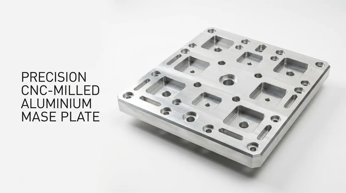
What Sets The Real Maximum Size (In The Order It Usually Bites)
When a part gets bigger, the constraint shifts from “can it fit?” to “can we hold it rigidly, reach every feature, and measure what matters?”
1) Work Envelope
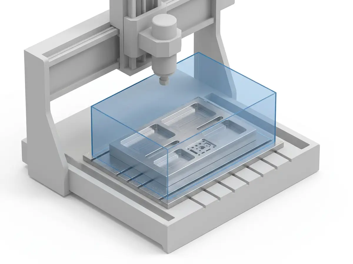
The machine travel (X/Y/Z) is the hard boundary. But usable travel is smaller once you add fixtures and tool clearance.
2) Tool Reach
Deep pockets and tall walls force long tools. Deflection shows up as taper, poor finish, and “mystery” tolerance drift.
3) Fixturing & Clamping
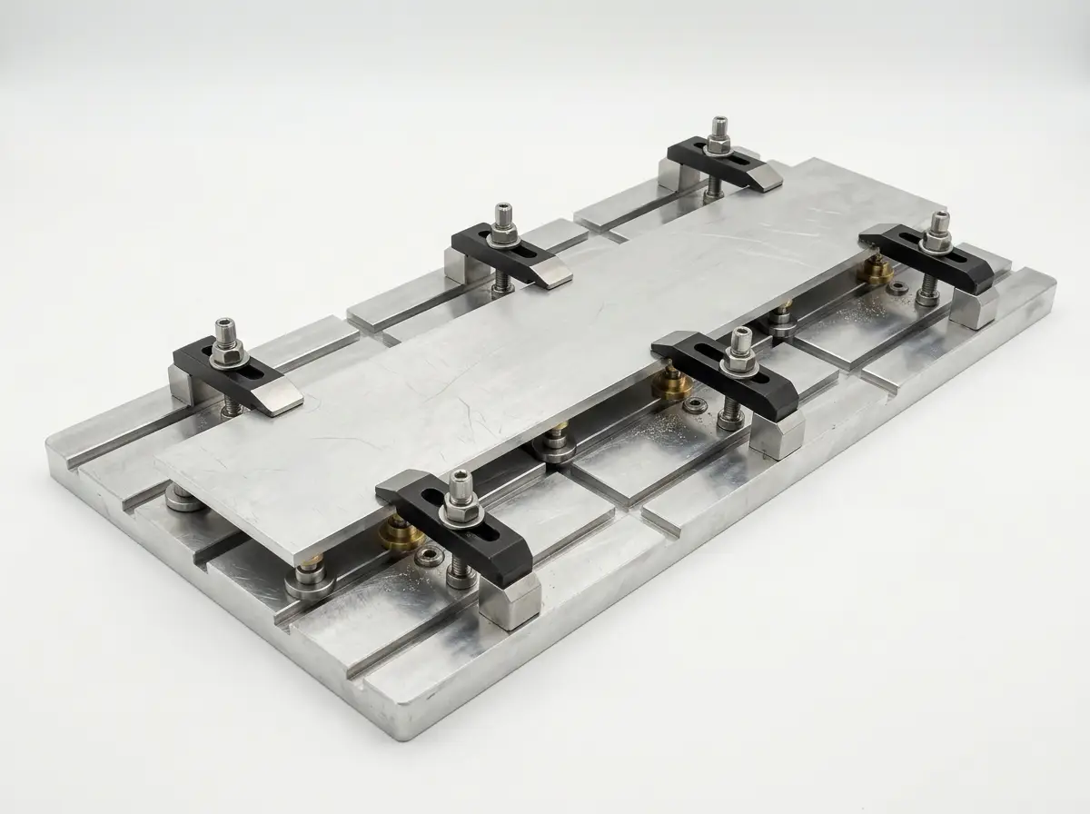
Large parts need support points and clamping that don’t distort critical surfaces. The fixture can be bigger than the part.
4) Rigidity & Vibration
Long spans behave like springs. Chatter risk rises fast, especially on thin webs and narrow ribs.
5) Thermal & Stress Movement
Roughing can release residual stress. If the part moves, the finishing pass can’t “put it back” without a plan.
6) Inspection Access
If you can’t probe the datums and features, you can’t prove the tolerance. Plan measurement early.
Large Part Design Checklist (Rules That Prevent Distortion And Rework)
Large parts fail quietly: a pocket looks fine in CAD, but the tool has to reach too deep, clamps bend the plate, or inspection can’t access the datums. These checks catch problems early.
| Design Feature | Practical Guideline | Why It Matters | Better Alternative |
|---|---|---|---|
| Long Thin Plates | Plan support points; avoid removing too much from one side before flipping. | Residual stress and uneven stock removal cause bowing. | Rough both sides, finish with a controlled sequence; add ribs where possible. |
| Deep Pockets | Keep pocket depth reasonable for tool reach; avoid narrow, very deep cavities. | Long tools deflect and chatter; corners drift and finish degrades. | Open the pocket, add access windows, or split into modules. |
| Datums | Define 3-2-1 datum scheme: primary plane, secondary edge/slot, tertiary point. | Large parts need a stable reference across setups and inspection. | Add datum pads, dowel holes, or reference bosses outside cosmetic areas. |
| Long Hole Patterns | Use datum-based GD&T callouts; avoid chaining dimensions over long spans. | Chained dims magnify tolerance stack and inspection ambiguity. | Baseline dimensions from datums; use position tolerance for patterns. |
| Large Flat Surfaces | Specify only the flatness you truly need; call out functional zones. | Flatness over long distance can drive extra operations and inspection time. | Define a “mounting land” zone; relax non-functional areas. |
When Your Part Is “Too Big”: Proven Design Moves That Keep Accuracy
If the part exceeds a stable setup, you have options that still preserve alignment, repeatability, and serviceability.
Split Into Modules
Divide the geometry along non-critical planes. Machine each module in a rigid setup, then align using datums.
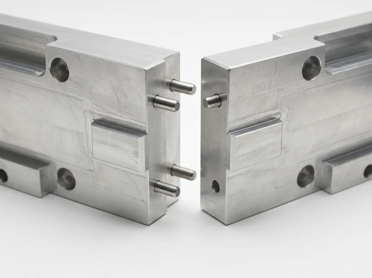
Include: dowel pins, precision shoulders, controlled gaps, and a repeatable assembly sequence.
Add Alignment Features
Use datum pads, keyways, bushings, or dowel patterns to lock translation and rotation.
Result: you can measure and correct each piece before final assembly.
Change The Starting Form
For very large structures, consider a weldment or casting with finish-machined datum interfaces.
Best Use: big volume + modest precision on non-functional surfaces.
A Simple Modular Interface That Works
Design the interface like a precision joint: one primary seating plane, one secondary locating edge, and a tertiary pin or boss to remove rotation. Keep fasteners for clamp force; use dowels for location.
If the assembly needs repeatability, add witness marks or asymmetric pin spacing to prevent misassembly.
Quality On Large Parts: Make The Datum Plan And Measurement Method Match The Size
Large parts can meet tight tolerances, but only when the datums are stable through machining, assembly, and inspection. Plan inspection like a feature, not an afterthought.
Datum Strategy
Pick functional surfaces as datums. Add datum pads if the functional surface is too large, thin, or cosmetic.
Critical Zones
Specify tight tolerances only where they drive performance: bearing seats, mounting lands, alignment faces, patterns.
Measurement Access
Ensure probes and tools can reach: avoid hidden datums or deep, narrow cavities that can’t be measured.
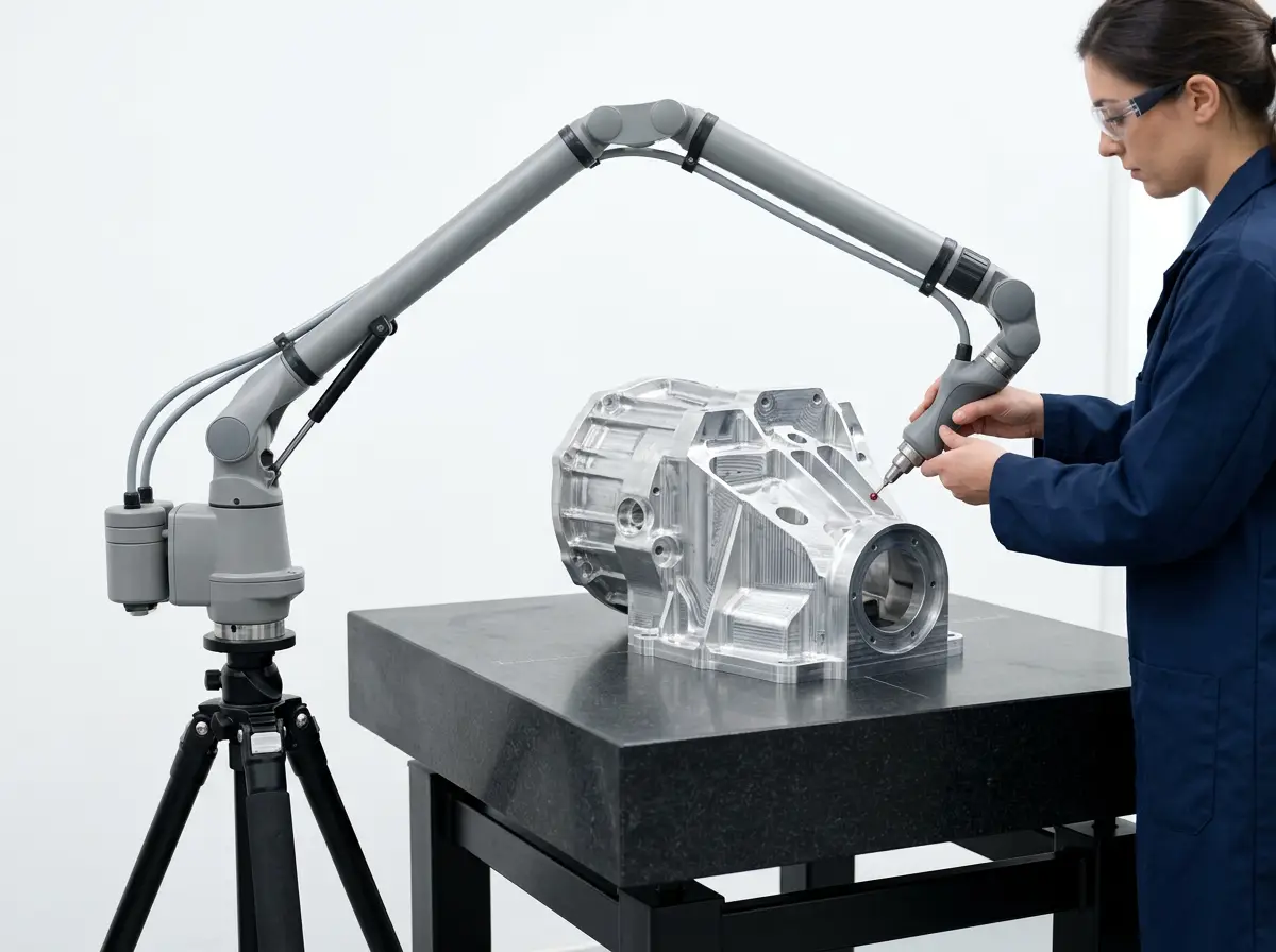
Quality On Large Parts: Make The Datum Plan And Measurement Method Match The Size
Large parts can meet tight tolerances, but only when the datums are stable through machining, assembly, and inspection. Plan inspection like a feature, not an afterthought.
Datum Strategy
Pick functional surfaces as datums. Add datum pads if the functional surface is too large, thin, or cosmetic.
Critical Zones
Specify tight tolerances only where they drive performance: bearing seats, mounting lands, alignment faces, patterns.
Measurement Access
Ensure probes and tools can reach: avoid hidden datums or deep, narrow cavities that can’t be measured.
Case Study: Long Alignment Plate For An Automation Station
A real-world example of turning an oversized, distortion-prone plate into a repeatable build using modular interfaces and a clear datum scheme.
Problem
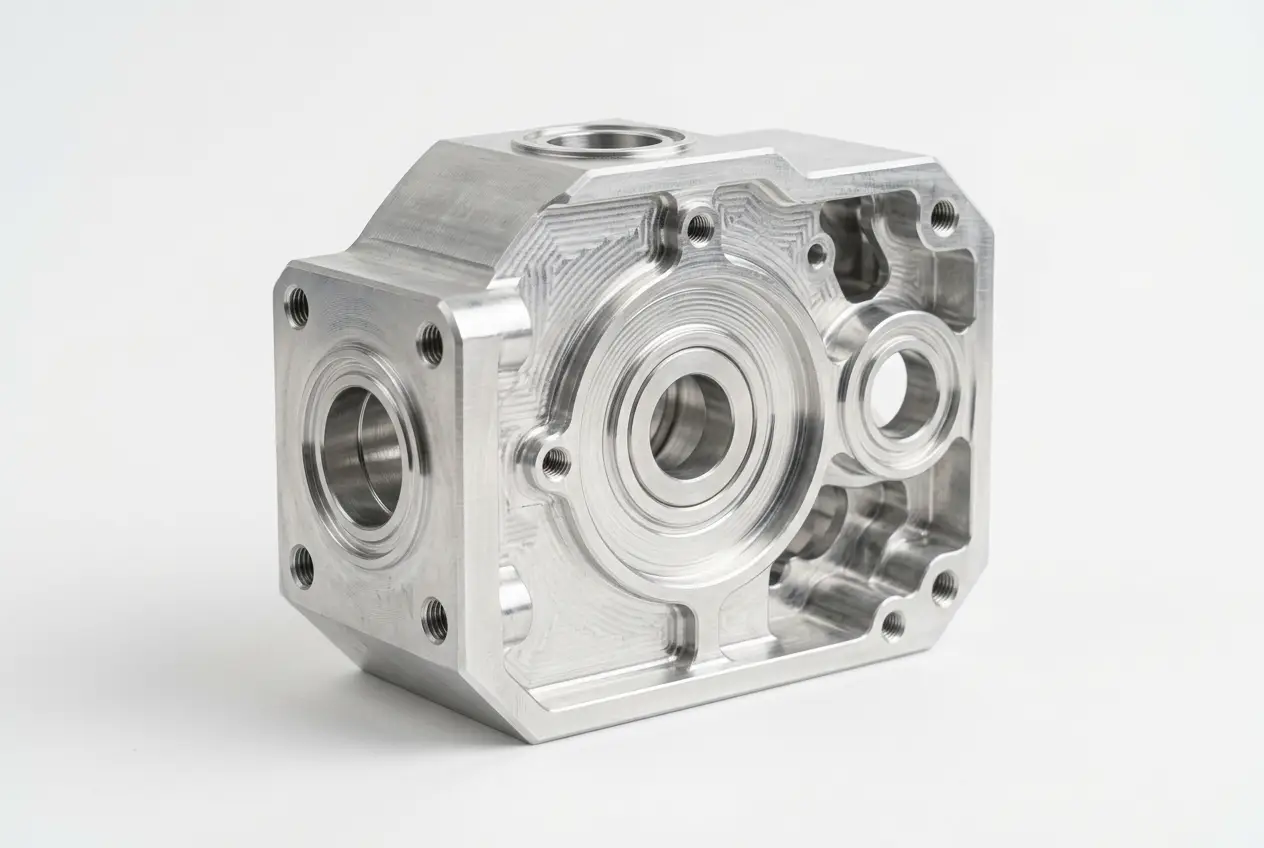
The customer needed a long, flat alignment surface with a hole pattern spanning a large distance. A one-piece design risked bowing after roughing and was difficult to measure consistently.
Solution
We redesigned the part into two rigid modules with a precision interface: seating plane + locating edge + dowel pins. We added datum pads outside the functional area and controlled the machining sequence to balance stress release.
Result
Each module could be machined and inspected in a stable setup. Assembly repeatability improved because location came from dowels, not fastener clearance.
Impact
The customer reduced risk on the critical alignment surface and gained a build they could scale: modules were easier to ship, rework, and replace without scrapping the full assembly.