
CNC Turning Guide — Section 01 Hero
CNC Turning Service For Custom Parts Precision CNC Turning Parts With Tight Tolerances CNC Turning Surface Finish And Roughness (Ra) Guide

CNC Turning Guide

If your part is round, concentric, threaded, or needs a clean bearing and sealing interface, turning is usually the shortest path to a dependable result. This guide explains how CNC lathe turning works, what drives cost and lead time, and how to choose tolerances and finishes that assemble right.

What You Get

Clear guidance on tolerances, surface roughness, threads, grooves, and inspection so you can quote once and move forward.

What We Focus On

Concentricity, runout control, datum strategy, and interface surfaces—where assemblies succeed or fail.

When To Go Hybrid

Turn the interfaces, mill the flats and cross-holes with live tooling—one setup plan, fewer surprises.
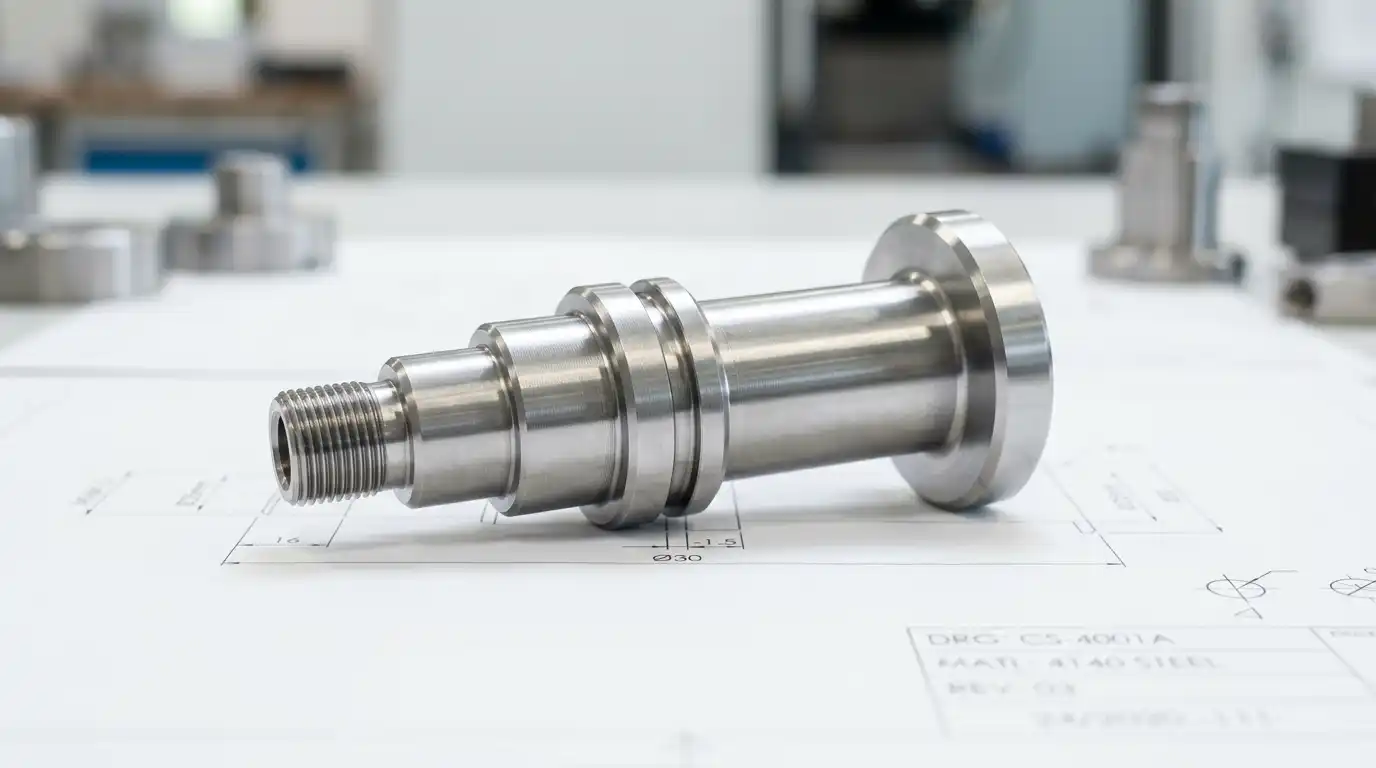
Precision CNC turned shaft hero

Tip: If a feature controls fit, call it out as critical. If it doesn’t, let it float—your quote (and delivery) will improve.

CNC Turning Guide — Section 02 Operations Overview

Operations Overview

CNC turning removes material by rotating the workpiece while a tool forms the outside diameter (OD), inside diameter (ID), faces, tapers, grooves, and threads. Modern turning centers can add live tooling for cross-holes, flats, and milled features—so one setup plan can produce a complete part.

OD / ID Turning

Control concentric features like shafts, bushings, bearing seats, and precision steps.

Grooving And Parting

O-ring grooves, snap-ring grooves, reliefs, and clean part-off geometry.

Threading

External and internal threads with proper lead-in and relief so assembly is smooth.

Boring And Reaming

Stabilize ID size and finish when the bore is a functional fit surface.

Knurling

Add grip surfaces or adjustment knobs when you need tactile interfaces.

Bar-Fed Turning

Efficient for repeat parts like spacers, retainers, and small shafts.

When Turning Is The First Choice

If your geometry is primarily rotational and your risk is fit, runout, and surface finish, turning typically delivers the fastest path to a stable interface. For complex non-round features, combine turning + live tooling or consider a hybrid plan.
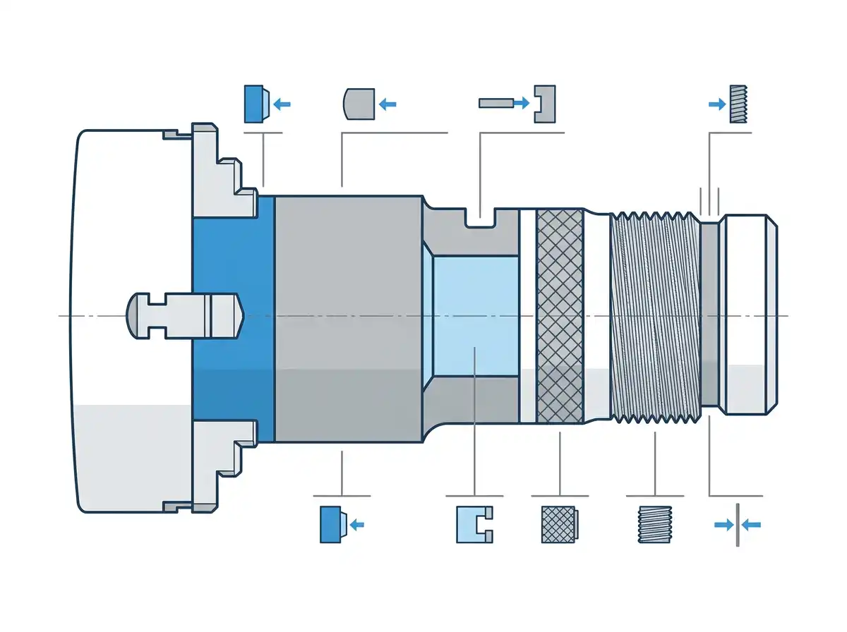
CNC turning operations diagram

Tip: If you can keep critical features in the same setup, you reduce stack-up and protect concentricity.

CNC Turning Guide — Section 03 How To Choose

How To Choose

If you’re deciding between CNC turning vs CNC milling how to choose, start by identifying what controls function: rotational interfaces (turning) or prismatic faces and pockets (milling). For long, slender, small-diameter parts, the question often becomes Swiss turning vs CNC turning when to choose.

Quick Decision Rules

Start With Turning when your critical features are concentric (shafts, bores, bearing seats), you need a clean surface finish, or threads and grooves drive assembly.

Start With Milling when your critical features are flats, pockets, patterns on faces, or complex 3D surfaces that don’t revolve around a centerline.

Use Swiss Turning when parts are small diameter and long relative to their diameter, especially when deflection/runout is the main risk.

Need / Risk Best Starting Process What To Watch
Concentric fits, runout control CNC Turning Keep critical diameters in one setup; define datums and inspection method.
Cross-holes, flats, milled slots Turning + Live Tooling Tool access and secondary milling orientation; avoid re-clamping if possible.
Small, slender parts (bar-fed) Swiss Turning Guide bushing strategy; material straightness; burr control.
Large prismatic features CNC Milling Tool reach, internal radii, and flatness on large faces.
Sealing faces and smooth cosmetic surfaces CNC Turning (Often With Finishing) Surface roughness callouts (Ra), masking, and handling marks.
CNC Turning Guide — Section 04 Design Guidelines

Design Guidelines

This section summarizes practical CNC turning design guidelines for grooves threads and undercuts. The goal is to keep tools rigid, minimize special operations, and make critical features measurable.

Keep Critical Diameters In One Setup

Concentricity and runout are easiest to protect when critical OD/ID features are finished without re-clamping.

Add Thread Relief And Lead-In

Give tools room to exit cleanly. Relief also improves assembly and reduces burr issues near shoulders.

Avoid Ultra-Thin Walls

Thin sections can deflect and chatter. When stiffness matters, add thickness or ribs instead of tightening tolerances.

FeatureRule Of ThumbWhy It Matters
Wall Thickness As a common baseline, avoid walls thinner than about 0.5 mm where possible. Thin walls vibrate, deflect, and can fail during machining or deburring.
Small Part Size Very small diameters and short lengths can be possible, but stability and handling become the main risks. Fixturing, tool access, and inspection can dominate the quote.
Threads Use standard thread sizes; provide a clear start chamfer and relief near shoulders. Prevents torn threads, tool rub, and assembly cross-threading.
Grooves Keep groove widths compatible with standard tooling; avoid razor-thin lands. Standard tools reduce cycle time and improve repeatability.
Edge Condition Specify edge break where needed; avoid “sharp everywhere.” Deburr scope impacts both time and cosmetic quality.

What To Send For A Clean Quote

For a CNC turning service for custom parts, include:

• STEP file (or native CAD)
• Drawing with critical fits and datums
• Material and any heat treat
• Surface finish requirements (Ra where functional)
• Quantity and target schedule
• Notes on “must-not-change” interfaces

Tip: If a dimension is functional, say how it functions (bearing fit, seal, alignment). It speeds up review and avoids wrong assumptions.

CNC Turning Guide — Section 05 Tolerances And Surface Finish

Tolerances And Surface Finish

For precision CNC turning parts with tight tolerances, the fastest way to stay on schedule is to apply tight requirements only to functional interfaces. Over-tolerancing expands inspection scope and can force special processes.

Practical Starting Point

Many CNC providers use a common default tolerance around ±0.13 mm (±0.005 in) unless otherwise specified. Higher precision (for critical fits) is achievable, but it changes the machining and inspection plan.

Surface Roughness (Ra) Guidance

A standard “as-machined” finish is often acceptable for non-functional surfaces. For sealing faces, bearings, or sliding interfaces, specify the roughness target and identify which surface is critical.
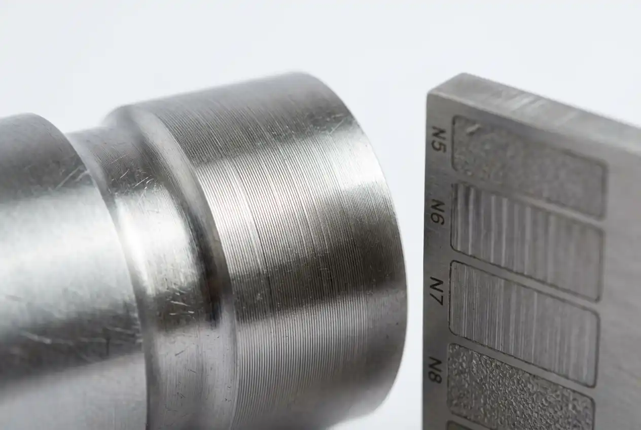
Turned surface finish close-up

Tip: Put the Ra callout only on the surfaces that matter. It protects function without inflating the whole quote.

General Tolerance Reference (ISO 2768 Example)

Nominal SizeMetals (Fine)Plastics (Medium)
0.5 mm to 3 mm±0.05 mm±0.1 mm
Over 3 mm to 6 mm±0.05 mm±0.1 mm
Over 6 mm to 30 mm±0.1 mm±0.2 mm
Over 30 mm to 120 mm±0.15 mm±0.3 mm
Over 120 mm to 400 mm±0.2 mm±0.5 mm

If you need guaranteed concentricity/runout, specify it with a datum strategy and plan inspection in advance.

CNC Turning Guide — Section 06 Materials And Finishes

Materials And Finishes

Material choice affects machinability, stability, corrosion resistance, and how well you can hold a surface finish. Below are common CNC turning materials aluminum stainless steel brass plastics used for shafts, housings, mounts, spacers, and precision interfaces.

Aluminum (6061 / 7075)

Great strength-to-weight. Use 7075 when stiffness and strength are critical; 6061 when general purpose and cost-efficient.

Stainless Steel (303 / 304 / 316 / 17-4)

Use for corrosion resistance and durability. 17-4 is popular for high strength after heat treat.

Brass

Excellent machinability and stable threads. Common for fittings, bushings, and low-friction components.

Engineering Plastics (POM, Nylon)

Lightweight, low friction. Specify where dimensional stability and moisture behavior matter.

Tool Steels

For wear surfaces, clamps, and high-load interfaces—often paired with heat treatment and finishing.

Finishes

Anodizing, bead blast, passivation, black oxide, and polishing. Mask critical fit surfaces when thickness matters.

CNC Turning Guide — Section 07 Cost And Lead Time Drivers

Cost And Lead Time Drivers

For CNC turning lead time and cost drivers explained, most quotes are controlled by time and risk: setups, cycle time, material behavior, and how much inspection is required to prove the result.

Setups

Each re-orientation adds clamping, touch-offs, and stack-up risk. Protect critical diameters by finishing them in one setup.

Cycle Time

Deep bores, narrow grooves, and interrupted cuts slow feeds and increase tool wear.

Inspection

More critical dimensions means more measurement. Decide what you must prove vs what can be standard.

Material

Hard or gummy alloys raise cutting time. Choose the simplest material that still meets strength and environment.

Finishing

Polish, masking, anodize, and cosmetic requirements add handling and schedule steps.

Quantity Path

Bar-fed turning scales well. If quantity may grow, design around standard tools and stable datums.

Fast Cost-Down Moves

• Put tight tolerances only on assembly interfaces
• Add chamfers and reliefs so tools can finish cleanly
• Use standard threads and avoid exotic groove forms
• Allow as-machined surfaces where possible
• Combine turning + live tooling to reduce secondary fixtures

CNC Turning Guide — Section 08 Inspection Evidence

Inspection Evidence

When a turned part is part of a robot joint, gearbox, or motion stack, the real requirement is often proof: measured diameters, bore size, runout, and feature location. Plan the inspection method early so tolerances are realistic and verifiable.

CMM Measurement

For datums, feature locations, and geometry verification on complex parts.

Pin / Plug Gauges

Fast go/no-go checks for bores when acceptance criteria is clear.

Runout Checks

Indicator-based checks for concentricity and rotational stability.

What We Can Provide

• First Article Inspection summaries
• CMM reports (when requested)
• Material certificates (when requested)
• Photo documentation for critical interfaces
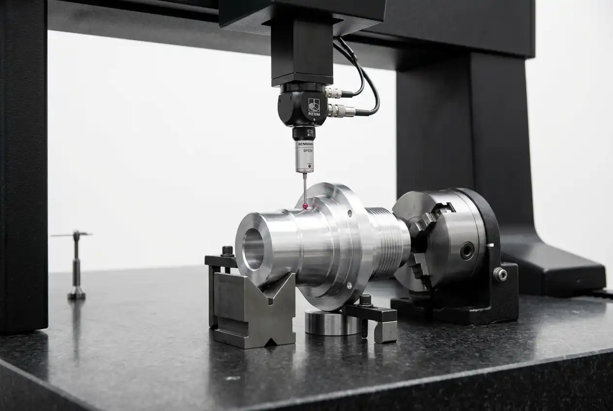
CMM inspection of CNC turned part

Tip: If you specify runout or concentricity, also specify datums—otherwise it’s hard to prove consistently.

CNC Turning Guide — Section 09 Case Study

Case Study: Shaft And Bushing Stack That Assembled Smoothly

This is a typical turning success pattern: keep the critical diameters and faces concentric, and the assembly works on the first build.

Problem

A rotating module had inconsistent fit between a shaft, spacer, and bushing stack. The design had “tight everywhere” callouts but no clear datum strategy for what actually controlled assembly.

Solution

We re-framed the part around functional interfaces: finishing critical OD/ID features in one setup, adding lead-ins and reliefs near shoulders, and defining inspection points that match assembly behavior.

Result

Fit became consistent and predictable, with smoother assembly and fewer rejects caused by burrs and stack-up.

Impact

The project moved from prototype iteration to stable repeat builds, with clearer inspection evidence and fewer back-and-forth questions during quoting.
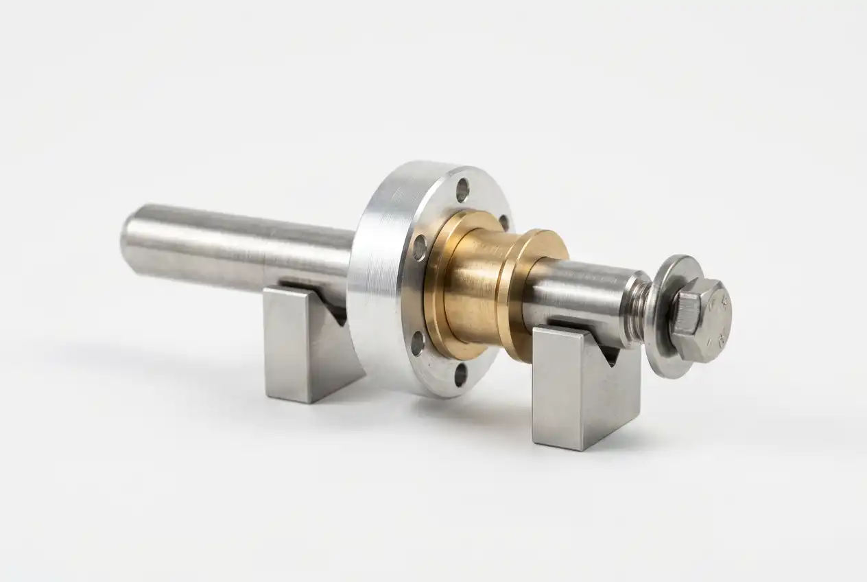
Turned shaft and bushing assembly case study

Key Lesson

Turning performs best when the drawing clearly separates critical fit surfaces from non-critical geometry—and keeps the critical surfaces measurable.

CNC Turning Guide — Section 10 FAQs

Frequently Asked Questions

Short answers for quoting, tolerances, threads, and what to expect from a CNC turning job.

What is CNC turning used for?
CNC turning is ideal for rotational parts such as shafts, bushings, spacers, bearing seats, threaded components, and concentric housings where fit and surface finish matter.
What tolerance can CNC turning hold?
A common default tolerance in many CNC quoting standards is around ±0.13 mm (±0.005 in) unless otherwise specified. Tighter tolerances are achievable on critical features, but they change the machining and inspection plan.
How do I specify surface finish for turning?
Identify the functional surfaces (seal, bearing, sliding). Put the roughness callout only on those surfaces, and keep non-critical surfaces as standard to protect cost and lead time.
Should I model threads in CAD?
For quoting, it’s often enough to call out thread specs clearly on the drawing. Add lead-in chamfers and relief near shoulders to improve manufacturability and assembly.
When should I choose Swiss turning?
Swiss turning is a strong choice for small-diameter, long, slender parts where deflection and runout are the main risks—especially when bar-fed efficiency matters.
Can you add cross-holes or flats on a turned part?
Yes. Turning centers with live tooling can drill and mill cross-features, flats, and slots in the same program, reducing secondary fixtures and stack-up.
What files should I send to get an accurate quote?
Send a STEP file (or native CAD), material and finish requirements, quantity, and a drawing that identifies critical interfaces, datums, and any special inspection needs.
Can you help improve my design before production?
Yes. We can propose manufacturability changes that protect function while reducing setup count, tool risk, and inspection burden—then confirm the impact on quote and lead time.
CNC Turning Guide — Section 11 How We Support Your Build

How We Support Your Build

Turning projects go smoothly when the drawing matches real assembly behavior. Our approach is simple: identify the interfaces that control fit, choose a stable setup strategy, and define inspection that proves what matters.

Our Default Approach

• Separate critical interfaces from non-critical geometry
• Finish critical diameters and faces in one setup when possible
• Add lead-ins, chamfers, and reliefs to reduce burr risk
• Align tolerances with measurable datums and inspection tools

What To Include In Your Message

1) Which surfaces are functional (bearing, seal, alignment)
2) Target quantity now and later
3) Environment (corrosion, heat, wear)
4) Any “must-not-change” geometry
5) Deadline and assembly constraints

You’ll get clearer feedback when intent is explicit.