
5-Axis CNC Machining For Complex, High-Precision Parts
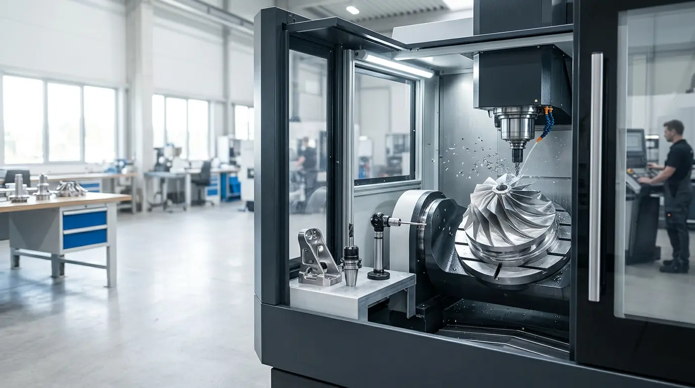
This guide explains 5 axis CNC machining in practical terms—when it reduces setups, improves feature-to-feature accuracy, and produces cleaner surfaces on contoured geometry. If you’re comparing 5 axis machining vs 3 axis, use the decision blocks below and then upload your CAD to confirm the best route.
Jump To What You Need
Quick links for engineers and sourcing teams comparing process options.
When To Choose 5-Axis Machining
5-axis is most valuable when it removes extra setups and protects critical relationships between features. It’s not “always better”—it’s better when geometry or GD&T would otherwise force multiple flips, custom fixtures, or long tools.
Choose 5-Axis When
Off-axis holes, angled faces, or multi-sided features must stay aligned to a functional datum scheme.
Choose 3+2 (Indexed) When
You need access to multiple sides and angled faces, but not continuous sculpted surfaces.
Choose 3-Axis When
The part is mostly prismatic, tolerances are moderate, and extra setups won’t break relationships.
What 5-Axis Typically Improves
Published guides consistently point to fewer setups, better surface finish on contoured geometry, and improved accuracy by reducing re-clamping and datum shift.
3-Axis Vs 3+2 Vs 5-Axis Continuous
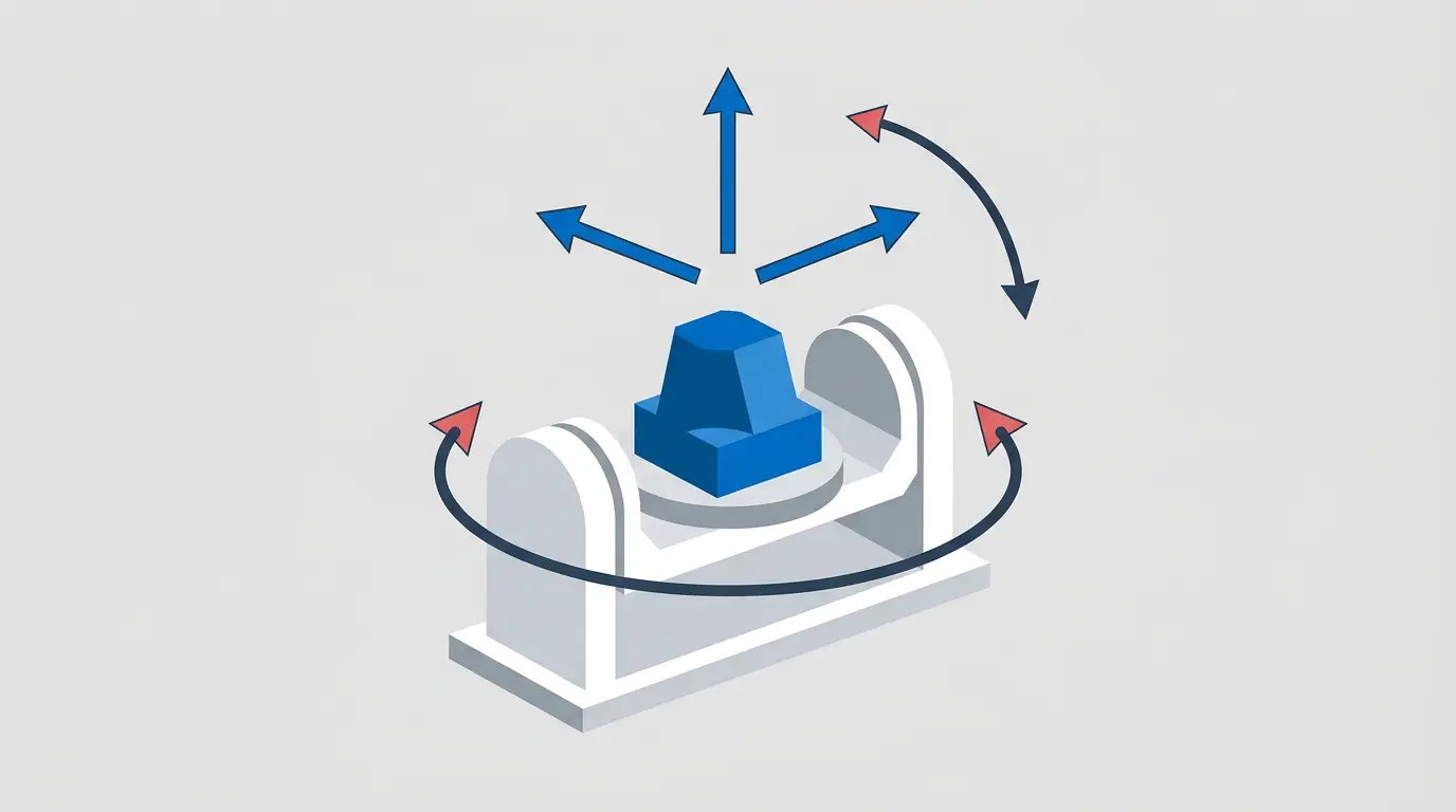
This breakdown matches how major manufacturers describe capability selection: indexed (3+2) positions the part, while continuous 5-axis moves all axes simultaneously for extreme contour control.
| Mode | What Moves During Cutting | Best Fit |
|---|---|---|
| 3-Axis | X/Y/Z only | Prismatic parts, simpler faces, fewer orientations |
| 3+2 (Indexed 5-Axis) | Rotary axes position, then X/Y/Z cut | Angled faces, multi-side access without extreme contours |
| 5-Axis Continuous | X/Y/Z + rotary axes move simultaneously | Complex contoured surfaces, fine features, tool-angle control |
Reference: Protolabs’ explanation of 3-axis vs 5-axis indexed vs 5-axis continuous; see external resources linked below.
Practical Rule
If you’re paying for multiple flips, custom fixtures, or long tools on a 3-axis route, 5-axis often becomes the simpler and more repeatable solution.
Design Tips For 5-Axis Success
A 5-axis machine can reach more angles, but it still needs clean tool access, stable workholding, and a datum scheme that reflects function. These tips reduce cycle time and inspection risk.
Protect Tool Access
Avoid trapped features that force long, slender tools; add relief where a cutter must enter/exit.
Stabilize Workholding
Add clamping flats or sacrificial tabs so the part can be held once without distortion.
Use Functional Datums
Define datums from interfaces that control assembly; it reduces ambiguity and inspection loops.
Right-Size Tolerances
Apply tight tolerances only where needed; many costs come from finishing and inspection, not just cutting.
What To Send For A Quote
STEP file, drawing with critical dimensions/GD&T, material/spec, finish, quantity, and a must-not-change list. This enables a DFM-forward quote that protects your functional intent.
Tolerance And Inspection Evidence
The most persuasive proof isn’t a claim—it’s a measurable plan. For high-precision 5-axis work, the evidence is typically: datum alignment, measurement method, and documented results on the features that matter.
Datum Strategy
We align setups to functional datums so critical feature relationships stay consistent in a single setup where possible.
Measurement Method
We select inspection methods appropriate to the tolerance (e.g., CMM for positional GD&T, gauges for bores).
Documented Outputs
First-article measurements and inspection records for key features can be provided upon request.
Typical Tight Tolerance Reference
Industry guides cite very tight capabilities for 5-axis under the right conditions (for example, some networks cite tolerances as tight as ±0.020 mm). Actual results depend on geometry, material, and inspection requirements—so we confirm feasibility from your CAD.
Case Study: Single-Setup 5-Axis Reduced Rework
This example illustrates how 5 axis machining advantages show up in real projects: fewer setups, better feature-to-feature alignment, and a smoother path to first-article acceptance.
Title
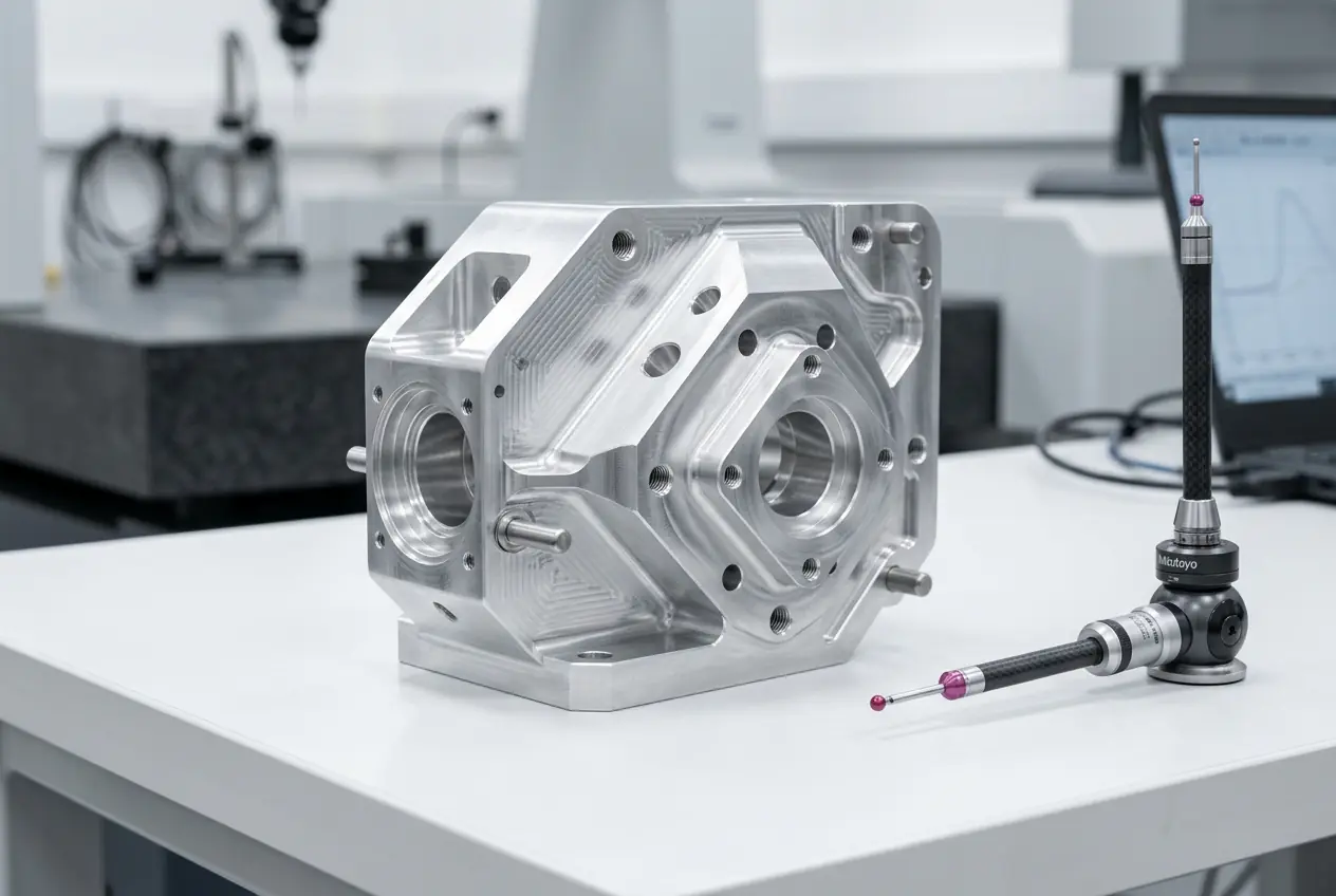
Robot Joint Housing With Off-Axis Bores: maintain alignment across angled faces and bearing features.
Problem
Multi-face features required multiple flips on a 3-axis route, creating datum shift risk and rework on bearing alignment.
Solution
Move to 3+2/5-axis strategy to reduce setups, keep tool shorter, and machine critical relationships in one holding.
Result
Cleaner feature alignment, fewer correction loops, and faster first-article convergence.
Impact
Lower total risk and a quote that better matched real manufacturability from the start.
What Made The Difference
Reducing re-clamping reduced opportunity for error. The win was consistency of critical relationships—not “more axes” for its own sake.

FAQ
Answers to common questions about 5 axis CNC machining tolerances, selection, and quoting.
What is 5 axis CNC machining?
When should I choose 5 axis machining vs 3 axis?
What is 3+2 machining vs 5 axis continuous?
Does 5 axis machining always cost more?
Can 5 axis machining improve surface finish?
What tolerances can 5 axis CNC machining achieve?
What should I include in my RFQ for 5 axis parts?
Can you review my design and recommend 3 axis, 3+2, or 5 axis?
Key Takeaways (Structured Summary)
Use these bullets as a clear summary for internal decision notes and quoting discussions.
Why 5-Axis
Fewer setups can reduce datum shift, protect feature relationships, and improve repeatability on complex parts.
What To Compare
Compare setup count, tool length/access, tolerance plan, and inspection method—not just machine hourly rate.
What To Send
STEP CAD + drawing with GD&T, material/spec, finish, quantity, lead time target, and must-not-change interfaces.
Next Step
Share your CAD and requirements to confirm the best machining approach and receive a quote aligned to your timeline.