
Why CNC Machined Parts Fail Inspection
This practical guide explains why CNC machined parts fail inspection—tolerance stack-up, datum and GD&T problems in CNC machining, and fit/finish issues that trigger costly rework. Use the diagnosis blocks below, then upload your CAD and drawing to prevent failures before they burn schedule and budget.
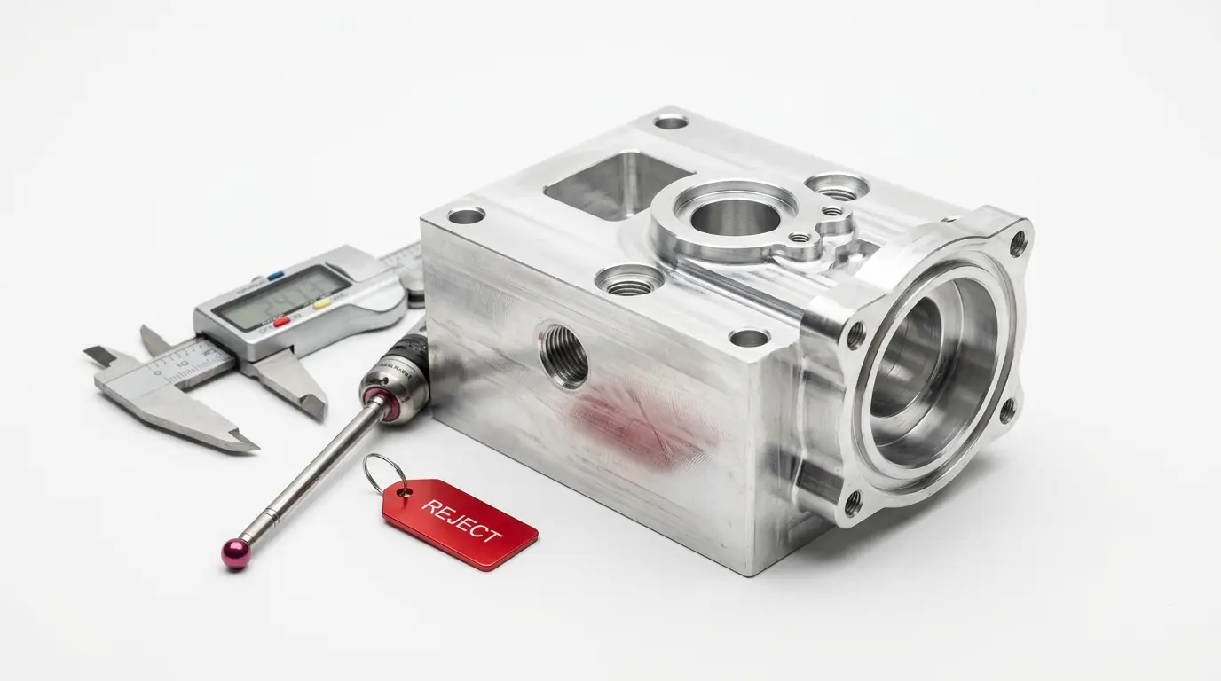
Jump To The Failure You’re Seeing
Most rejects cluster into a few repeatable categories. Use the quick links to get directly to the fix checklist.
Diagnosis Matrix: What Failed, What Usually Caused It, What To Change
Use this table when you’re under time pressure. It maps the most common inspection failures to the root causes and the fastest fixes.
| Failure Symptom | Common Root Cause | Fastest Fix |
|---|---|---|
| Assembly Doesn’t Fit | Uncontrolled functional stack-up; tolerances applied per-feature but not per-interface. | Define the functional datum scheme and control feature-to-feature relationships; loosen non-critical faces. |
| Position/Profile GD&T Fails | Datum selection doesn’t match how the part is located in assembly; incomplete datum reference frame. | Choose datums from assembly interfaces; complete the datum frame; ensure basic dimensions match the GD&T approach. |
| Surface Finish Rejected | Chatter/tool marks; unclear cosmetic zones; missing edge break or deburr requirements. | Specify finish only where needed; add deburr/edge-break notes; adjust tool strategy for finishing surfaces. |
| Flatness/Parallelism Fails | Part distortion from clamping or residual stress; machining sequence not aligned to stability. | Add stability features/ribs where allowed; use staged machining and stress-relief strategy for sensitive parts. |
| CMM Shows Failure But Part Works | Inspection alignment doesn’t match functional datums; measurement strategy mismatch. | Align inspection to the same datums as the drawing/assembly; confirm measurement plan and sampling strategy. |
Fastest Way To Stop Repeat Rejects
Upload CAD and the drawing. A short DFM/inspection-readiness review can identify the few features and notes that prevent repeated interpretation and rework loops.
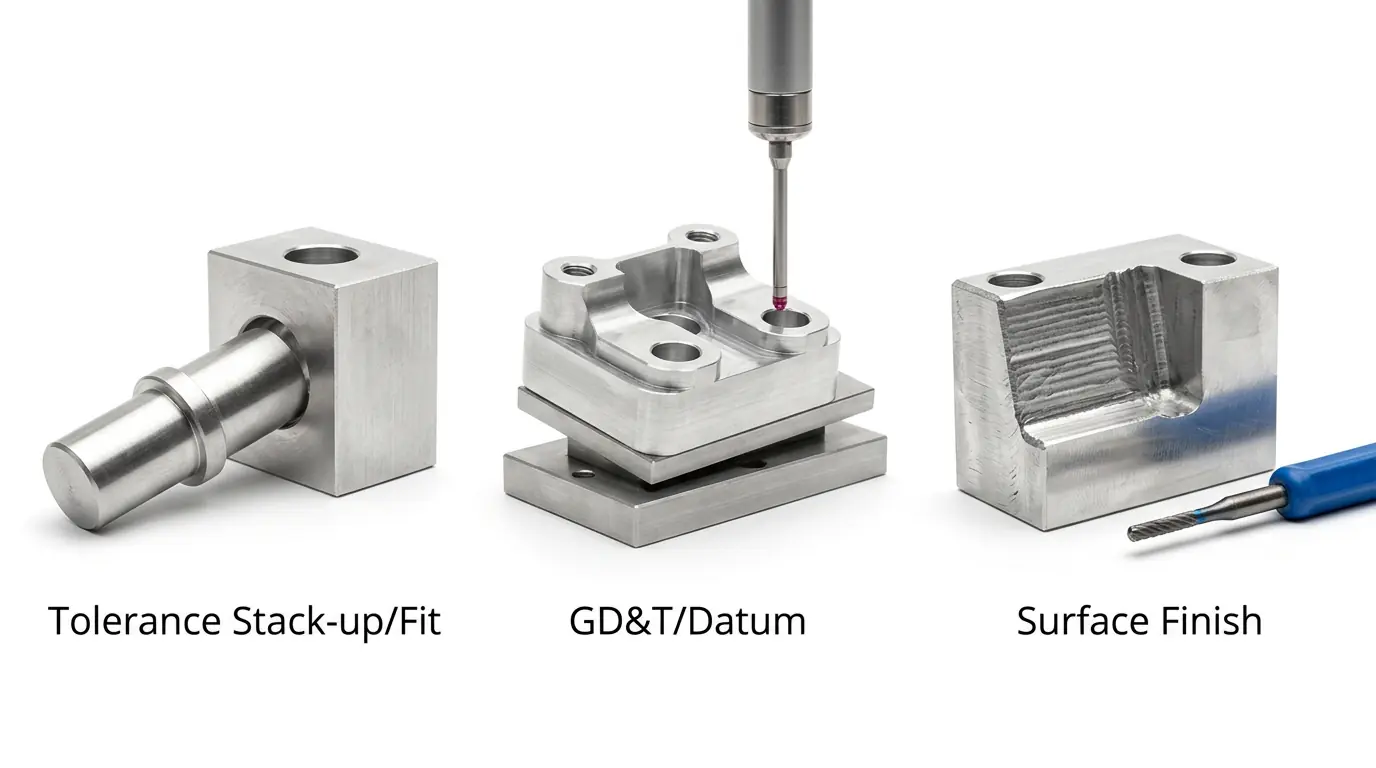
Tolerance Stack-Up: When Every Feature Passes But The Assembly Fails
Stack-up failures happen when a set of individually acceptable deviations combine at the functional interface. The fix is not “tighter tolerances everywhere”—it’s controlling the stack path with the right datums and relationship controls.
Common Triggers
Overconstrained dimensions, missing functional datums, multi-setup drift, and tolerance applied to the wrong surfaces.
How To Diagnose
Identify the interface that must fit, then trace the chain of features that locates it. That chain is your stack path.
How To Prevent
Control the relationship between the locating features and the interface. Loosen everything that doesn’t affect function.
GD&T And Datums: The Most Common Source Of False Rejects
Across published guidance, recurring pitfalls include weak or unstable datums, incomplete datum reference frames, and mixed signals between basic dimensions and toleranced dimensions. When the datum scheme doesn’t mirror assembly, the part can be measured “wrong” even if it functions.
Choose Functional Datums
Use the surfaces that locate the part in the real assembly, not whatever is easiest to measure.
Complete The Datum Frame
Primary only is rarely enough; constrain remaining degrees of freedom to remove ambiguity.
Avoid Mixed Signals
Basic dimensions should pair with GD&T controls; inconsistent dimensioning drives interpretation fights.
Right-Size Controls
Over-tolerancing increases cost and rejection without improving function.
Fit And Finish Issues: Tool Marks, Burrs, And Unclear Cosmetic Zones
Finish rejects often happen because requirements are implied rather than specified. Define where finish matters, how edges should be treated, and what “acceptable” looks like for functional vs cosmetic faces.
Tool Marks And Chatter
Often driven by tool overhang, weak setups, or aggressive finishing passes. Specify finishing faces and allow proper finishing strategy.
Burrs And Edge Break
Missing edge requirements can turn into safety and assembly issues. Add explicit deburr/edge-break notes and critical edge callouts.
Finish Zones
Make cosmetic areas explicit. Keep as-machined acceptable where the surface is not function-critical.
Inspection Method: When Measurement Strategy Creates Scrap
Inspection is a process, not a single measurement. If alignment, probing, or datum simulation does not match the drawing intent, results can vary wildly across shops.
Align To Datums
Ensure CMM alignment mirrors the drawing’s datum reference frame and assembly intent.
Define The Method
For critical features, specify how to verify (gauge vs CMM vs functional test) when appropriate.
Manage Uncertainty
Very tight tolerances demand a measurement strategy that can actually resolve the requirement.
Use FAI Wisely
First-article results should validate the datum scheme and process; then you can move to sampling where acceptable.
Case Study: Preventing A False Reject On A Datum-Sensitive Part
This case shows how a datum mismatch can look like a manufacturing problem when it’s actually an inspection alignment problem—and how to prevent the loop.
Title
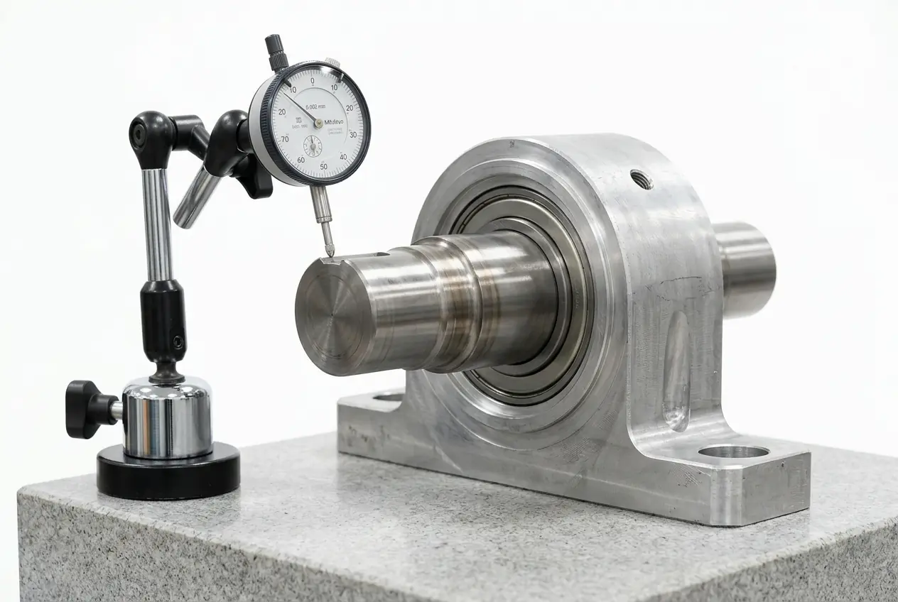
Bearing Seat And Shaft Alignment: avoid repeated position failures by aligning datum scheme, machining plan, and inspection method.
Problem
Incoming inspection flagged positional failure on a hole pattern; assembly behavior was inconsistent across lots.
Solution
Re-define functional datums from the assembly interfaces, clarify basic dimensions, and align CMM setup to the datum reference frame intent.
Result
Consistent inspection outcomes and fewer rework loops, with interfaces verified against the functional stack.
Impact
Reduced scrap risk and schedule loss by removing ambiguity from the drawing and measurement method.

FAQ
Quick answers about CNC inspection failure causes, stack-up, GD&T, and prevention.
What are the most common CNC inspection failure causes?
Why do parts fail assembly even when dimensions pass?
How do datums cause false rejects?
Should I tighten tolerances to prevent failures?
What GD&T mistakes cause the most inspection confusion?
How do I prevent surface finish rejects?
Can inspection method change pass/fail results?
Can you review my CAD and drawing to prevent inspection failures?
Key Takeaways (Structured Summary)
Use these bullets as a clear summary for internal decision notes and quoting discussions.
Root Causes
Most rejects trace back to stack-up control, datum/GD&T clarity, finish/edge definitions, or inspection alignment.
Fastest Fix
Define functional datums, control interface relationships, and loosen non-critical requirements that create inspection burden.
Quote Inputs
CAD + drawing, critical interfaces, must-not-change list, finish zones, quantity, and inspection expectations.
Next Step
Upload CAD and the drawing to identify the likely failure mode and prevent repeat rejects before production is blocked.