
CNC Milling Guide — Section 01 Hero
CNC Milling Design Guidelines For Engineers CNC Milling Tolerances And Surface Finish Guide 3-Axis Vs 5-Axis CNC Milling When To Choose

CNC Milling Guide: Design, Tolerances, Cost, And Practical Decisions

This guide helps you make confident milling decisions: choose the right process, set tolerances that match function, and avoid geometry that forces extra setups. If your goal is How to reduce CNC milling cost and lead time, start by marking CTQs, simplifying tool access, and selecting an inspection plan that matches approvals.

What You’ll Learn

Core rules like internal corner radius, pocket depth, wall thickness, and how they affect tooling and cycle time.

What You Can Prove

How to define datums, CTQs, and inspection evidence (CMM, first article checklist) for approvals.

What To Do Next

Upload CAD to get a process recommendation and a DFM-first machining plan for your part.
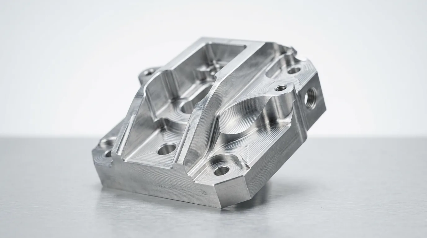
5-axis CNC milling aluminum part

Tip: Start from CTQs. Tighten only what gates function, and leave everything else manufacturable.

CNC Milling Guide — Section 03 Geometry Rules

Geometry Rules That Control Milling Cost And Quality

Milling outcomes are decided by tool access and stiffness. These rules are practical defaults used by many CNC suppliers. They support Pocket depth and wall thickness rules for CNC milling and Internal corner radius rules for CNC milling parts.

Internal Corner Radius

Inside corners will be radiused by the tool. Larger radii enable larger cutters and faster feeds.

Rule: Avoid “sharp internal corners”; redesign interfaces or use undercut features only when required.

Pocket Depth Ratio

Deep pockets force long tools, which increases chatter risk and slows cycles.

Rule: Keep pockets shallow when possible; split depth into steps or redesign the cavity.

Thin Walls

Thin walls flex and chatter; they can warp after finishing.

Rule: Use ribs, increase thickness, or change orientation to support machining stiffness.

Small Holes And Deep Holes

Micro holes and deep drilling add time and break tools more easily.

Rule: Use standard drill sizes and avoid very deep holes unless function requires it.

Design Rule Snapshot (Engineer-Friendly)

FeaturePreferred Design DirectionWhy It Matters
PocketsKeep depth modest; avoid extreme depth-to-widthReduces long tools, chatter, and cycle time
Internal CornersAdd generous radius or redesign interfaceEnables larger tools and faster machining
WallsUse ribs or thicker walls where loads existImproves stiffness, reduces vibration marks
ThreadsUse standard thread sizes; call out thread spec in drawingImproves tool availability and inspection clarity
Practical Tip: If you need one face to be perfect (seal, optical, bearing seat), isolate that face as a CTQ and loosen everything else. That single step often delivers How to reduce CNC milling cost and lead time without sacrificing performance.
If a feature is hard to machine, it’s usually hard to measure. Make CTQs easy to inspect to avoid cost inflation.

Reference basis used by many suppliers includes pocket depth/diameter ratios and tolerance practicality published by established CNC manufacturing guides.

CNC Milling Guide — Section 04 Tolerances And Inspection

Tolerances, Datums, And Inspection Evidence

Tight tolerance is not “better” by default. It is a tool you use on CTQs to control function. Many suppliers publish standard tolerances and recommend tightening only where necessary—because tighter tolerances increase cycle time, scrap risk, and inspection effort. This section supports CNC milling tolerances and surface finish guide decisions.

How To Apply Tolerances Without Overpaying

What To DoWhy It WorksTypical Outcome
Mark CTQs (fit, seal, alignment)Focuses machining + inspection on functionLower cost without functional risk
Use clear datum schemeReduces setup ambiguity and stack-up problemsMore repeatable assemblies
Loosen non-CTQ featuresEnables faster tooling and fewer inspectionsShorter lead time
Match inspection evidence to approvalAvoids expensive “measure everything” plansQuote reflects real requirements

Evidence Levels Buyers Commonly Request

EvidenceBest ForWhat You Provide
Basic Dimensional CheckSimple prototypes and non-critical fitsKey dimensions verified; deburr confirmation
CMM Inspection ReportDatum-driven geometry and CTQ boresMeasured CTQs with traceable equipment
First Article ChecklistPilot builds and approvalsBallooned drawing + characteristic verification

If you need CNC milling inspection plan CMM and first article checklist support, the fastest path is to upload CAD and highlight CTQs.
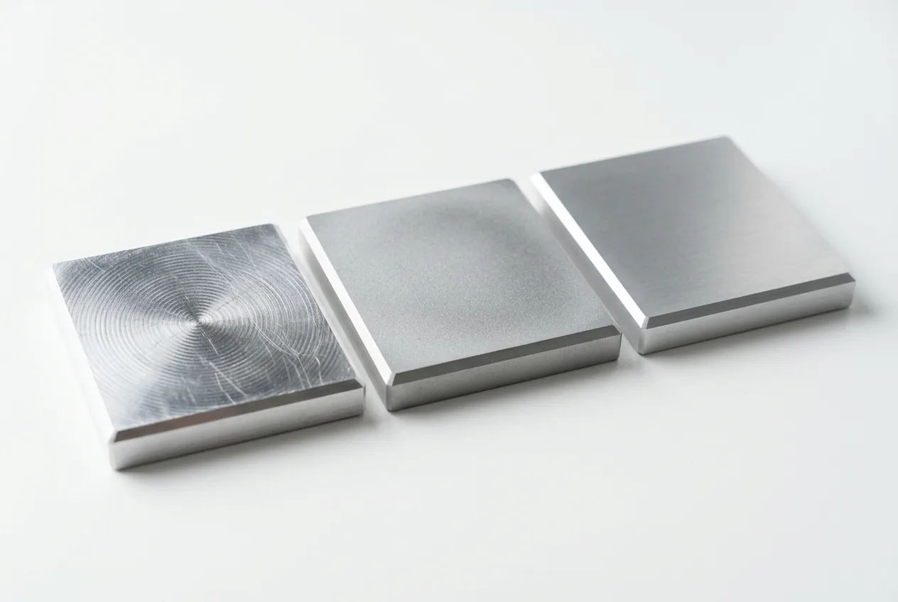
Machined surface finish and inspection context

Inspection-Friendly Design Moves

Use datums that can be probed, avoid hidden measurement features, and keep CTQ surfaces accessible. If it can’t be measured reliably, it can’t be approved reliably.

CNC Milling Guide — Section 05 Cost And Lead Time

Cost And Lead Time Drivers In CNC Milling

Milling cost comes from setup + machining time + finishing + inspection. Quotes increase when suppliers must guess CTQs, datums, or surface finish. This section supports How to reduce CNC milling cost and lead time and CNC milling DFM checklist before RFQ intent.

Five Levers That Usually Reduce Cost

Reduce setups by aligning features and using fewer orientations.
Simplify toolpaths by using generous radii and avoiding deep pockets.
Tighten only CTQs; loosen non-functional tolerances and finishes.
Use standard holes/threads to avoid special tooling and inspection overhead.
Match evidence to approvals (basic check vs CMM vs first article checklist).

What To Provide For Fast, Accurate Quoting

InputWhy It Lowers Risk Padding
CAD + 2D drawing for CTQsRemoves tolerance ambiguity and defines datums.
Quantity and lead time targetEnables the right process plan and batching strategy.
Material and acceptable alternatesLets sourcing optimize availability and machinability.
Finish requirements and cosmetic zonesPrevents over-finishing non-functional faces.
Inspection evidence levelAligns inspection time with your approval process.

Three-Axis Vs Five-Axis: A Cost Reality Check

3-axis can be very cost-effective when your part completes in one or two stable setups. 5-axis can reduce cost when it replaces many setups, improves tool access, and avoids custom fixtures.

Common Hidden Adders

Very tight tolerances on non-CTQ faces, deep narrow pockets, long tool stick-out, and hard-to-measure geometry.

CNC Milling Guide — Section 06 Materials And Finishes

Materials And Finishes That Affect Milling Outcomes

Choosing materials and finish requirements early prevents rework loops. Some materials are harder to hold tight tolerances due to flexibility or machining behavior. This section supports Best CNC milling materials for prototypes and production and CNC milling tolerances and surface finish guide intent.

Material Selection Snapshot

Material FamilyBest ForWatchouts
Aluminum (e.g., 6061/7075)General structures, housings, brackets, prototypesThin walls can chatter; define cosmetic zones
Stainless SteelCorrosion resistance, wear, strengthLonger machining time; consider finish allowance
Tool SteelWear-critical fixtures and insertsMay require heat treat planning and finish machining
Engineering PlasticsInsulators, wear pads, lightweight componentsFlex can make tight tolerances harder to hold

Finish Selection Snapshot

FinishWhen To UseWhat To Specify
As-MilledFunctional prototypes; internal facesAllow tool marks; define non-cosmetic areas
Bead BlastUniform matte cosmeticsMask CTQ fits; maintain datums
AnodizeWear/corrosion resistance on aluminumDefine thickness and mask critical fits if needed
Passivation / PlatingStainless corrosion and protectionSurface requirement and masking zones

Surface Roughness (Ra) In Plain Terms

Surface roughness is the “texture” left by cutting and finishing. For sealing, sliding, and bearing seats, specify roughness on the functional face only. For non-functional faces, avoid over-controlling finish.

Finish Allowance Rule

If you plan anodize, bead blast, or polish, reserve allowance on cosmetic faces and protect critical fits. That keeps CTQs stable after finishing.

CNC Milling Guide — Section 07 Case Study

Case Study: Milling Plan That Cut Rework And Improved Alignment

A customer needed a precision bracket/plate set where hole patterns and bearing seats had to align during assembly. The first prototype fit-check failed due to datum ambiguity and hard-to-inspect CTQs.

Problem

Multiple setups introduced small positional shifts, and the drawing did not clearly identify CTQs and datum references. Inspection effort increased but still did not prevent rework.

Solution

We clarified the datum scheme, marked CTQs (bearing seat and hole pattern), and revised geometry to improve tool access. The process plan reduced setup count and aligned inspection to the approval-critical features.

Result

First-article fit improved and the assembly aligned without hand fitting. Inspection became faster because CTQs were measurable and clearly defined.

Impact

Fewer rework loops, faster engineering approvals, and a cleaner path to repeat orders with stable process capability.
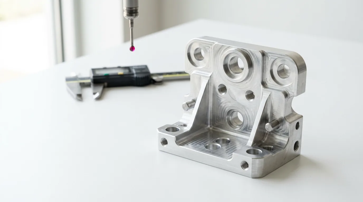
Precision milled bracket alignment case study

What Made It Work

Clear CTQs, fewer setups, and inspection that matches how the assembly is actually approved.

CNC Milling Guide — Section 08 FAQ

FAQ

Quick answers for engineers choosing milling, setting tolerances, and preparing quote-ready packages.

What Is The Difference Between CNC Milling And CNC Turning?
Milling uses rotating cutters to create flats, pockets, and complex 3D surfaces, while turning spins the part to create round features like shafts, bores, and diameters. Many assemblies use both.
What Tolerances Are Realistic For CNC Milling?
Realistic tolerances depend on geometry, setup count, tool access, and material. Tighten only CTQs; keep non-functional features looser to reduce cost and inspection time.
How Do Internal Corner Radii Affect Milling Cost?
Small inside radii force small tools and longer machining time. Larger radii allow bigger cutters, higher feed rates, and better tool life.
When Should I Choose 5-Axis Milling?
Choose 5-axis when it reduces setups, improves tool access, and protects surface quality on complex angles. If a part completes in one or two stable setups, 3-axis may be more cost-effective.
What Surface Finish Should I Specify?
Specify surface roughness (Ra) only on functional faces (seal, slide, bearing). For non-functional faces, allow as-milled or cosmetic finishing without over-control.
How Can I Reduce Lead Time For CNC Milling?
Reduce setup count, simplify geometry, use standard holes/threads, and provide clear CTQs and datums. Ambiguity increases engineering back-and-forth and inspection time.
What Should I Include In A Quote-Ready Package?
Send CAD + 2D drawing, quantity, target lead time, material (and alternates), finish requirements, CTQs, and inspection evidence level. This prevents risk padding in quotes.
Can You Provide CMM Reports Or First Article Checklists?
Yes. If your approval process requires formal evidence, specify the CTQs and the evidence level you need. This aligns the machining plan, inspection plan, and documentation from the start.
CNC Milling Guide — Section 09 Final Notes

Practical Notes For Buyers And Engineers

Batnon supports milling programs by turning requirements into a stable process plan: CTQs, datums, setup strategy, and inspection evidence. If you’re comparing suppliers, the fastest path is to share your CAD and highlight the interfaces that gate function—fits, seals, alignment, and bearing seats.

Typical requests include CNC milling design guidelines for engineers, CNC milling tolerances and surface finish guide questions, and 3-axis vs 5-axis CNC milling when to choose decisions. If your goal is repeatable approvals, define the evidence package you need (basic checks, CMM report, or first article checklist) so the quote reflects reality instead of uncertainty.